Appearance
Structure Analysis
Structure analysis is the second step of FMEA analysis, with the goal of defining the analysis scope, building hierarchical structure, and constructing the basic skeleton for analysis. This guide explains how to perform structure analysis.
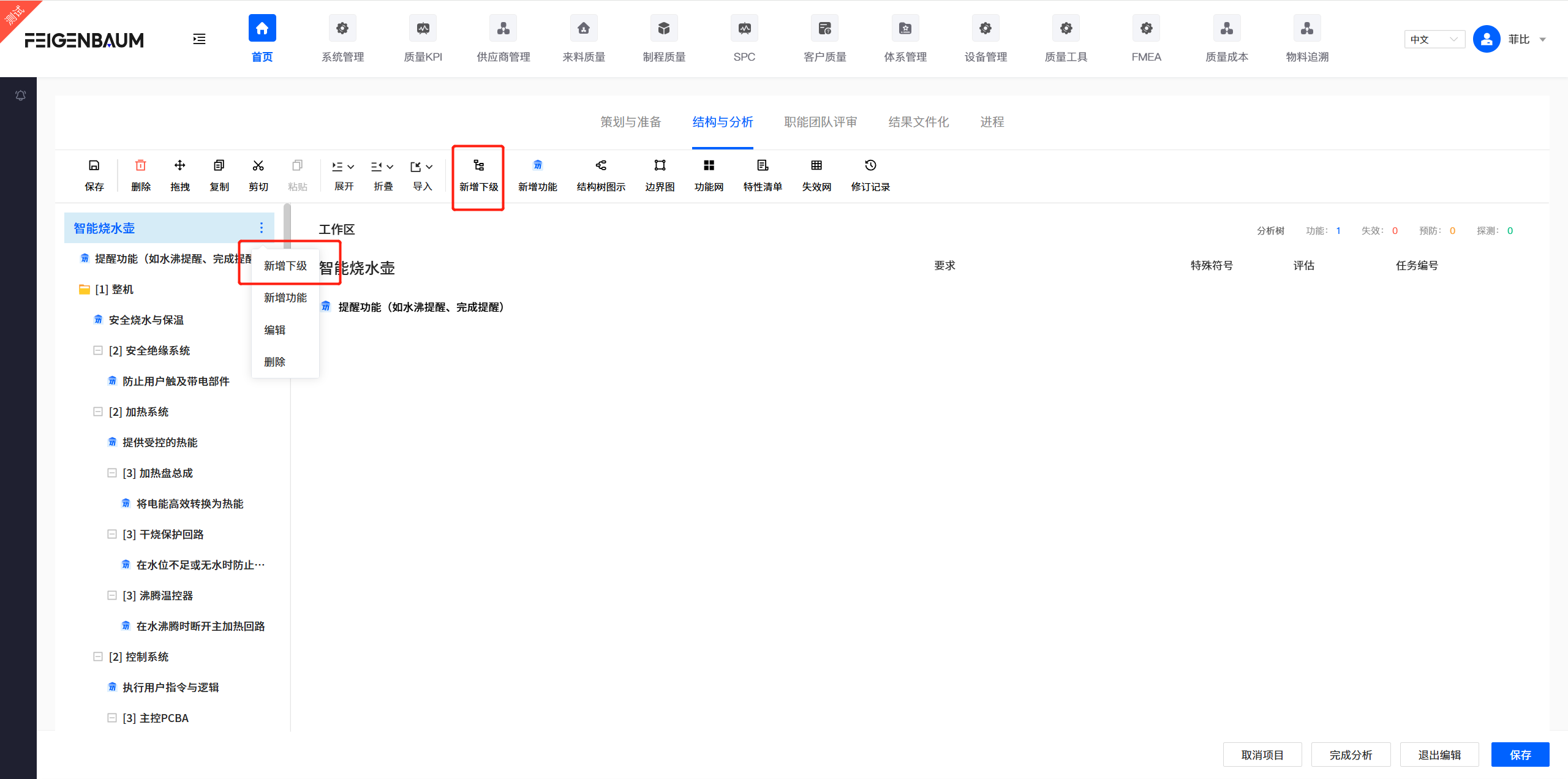
Hierarchical Structure
- Goal: Define analysis scope, build hierarchical structure, construct basic skeleton for analysis.
- Role: Implementation role member
- Operations:
- Click "Add Same Level/Add Sub Level", start from the highest level (system), decompose step by step to the lowest level (parts/process elements).
- Drag elements to adjust hierarchical relationships.
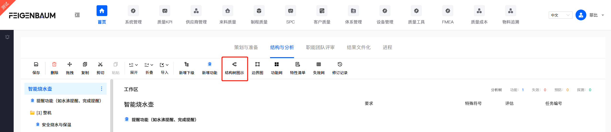
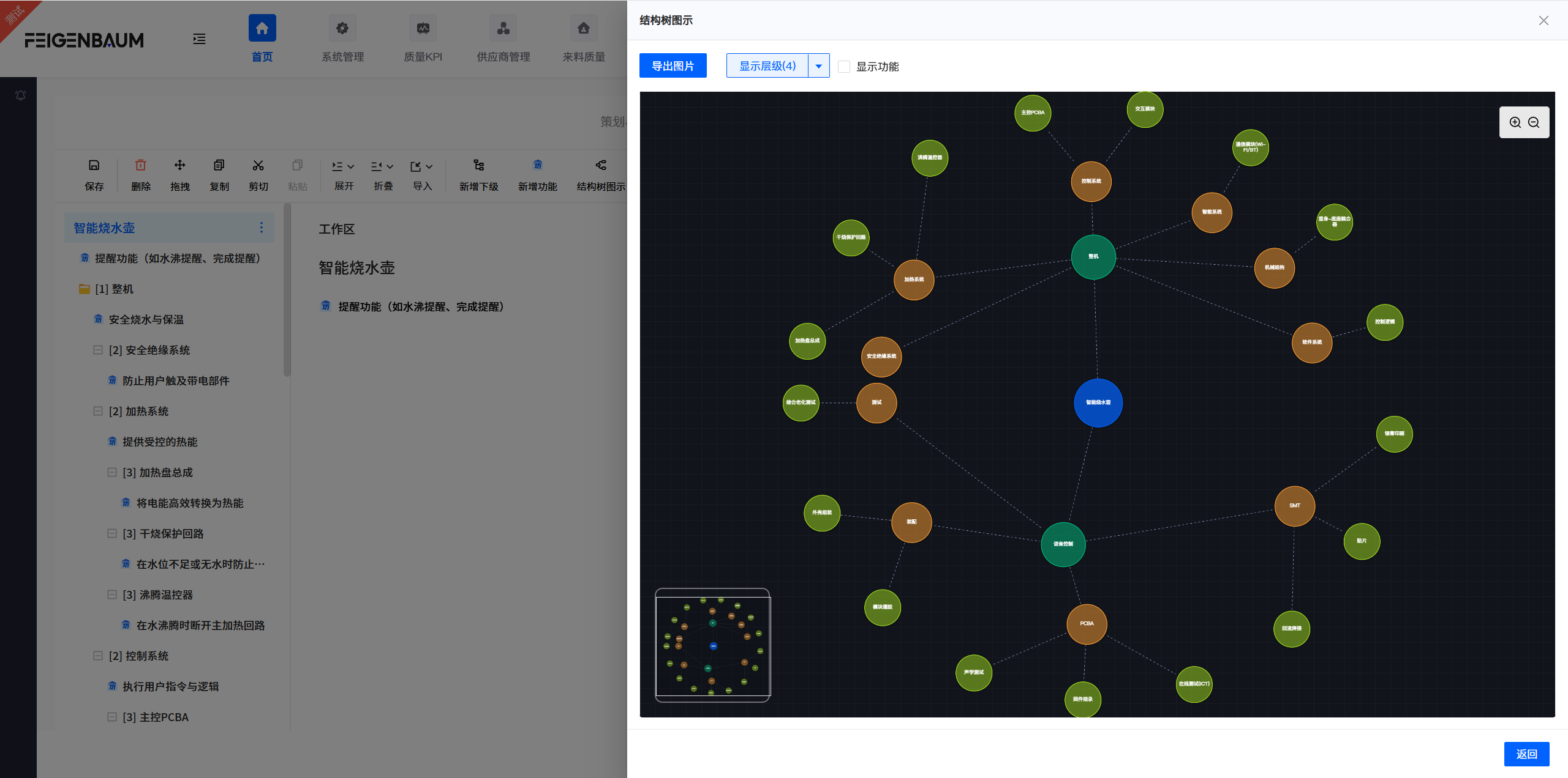
Structure Tree
Structure tree is a graphical tool for displaying dependencies between structural levels, helping you understand the system's composition and hierarchical relationships more clearly.
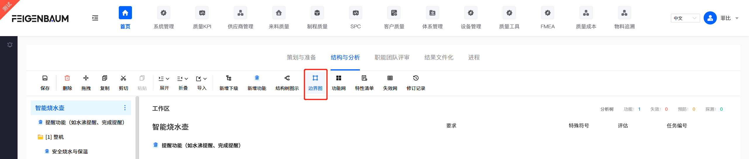
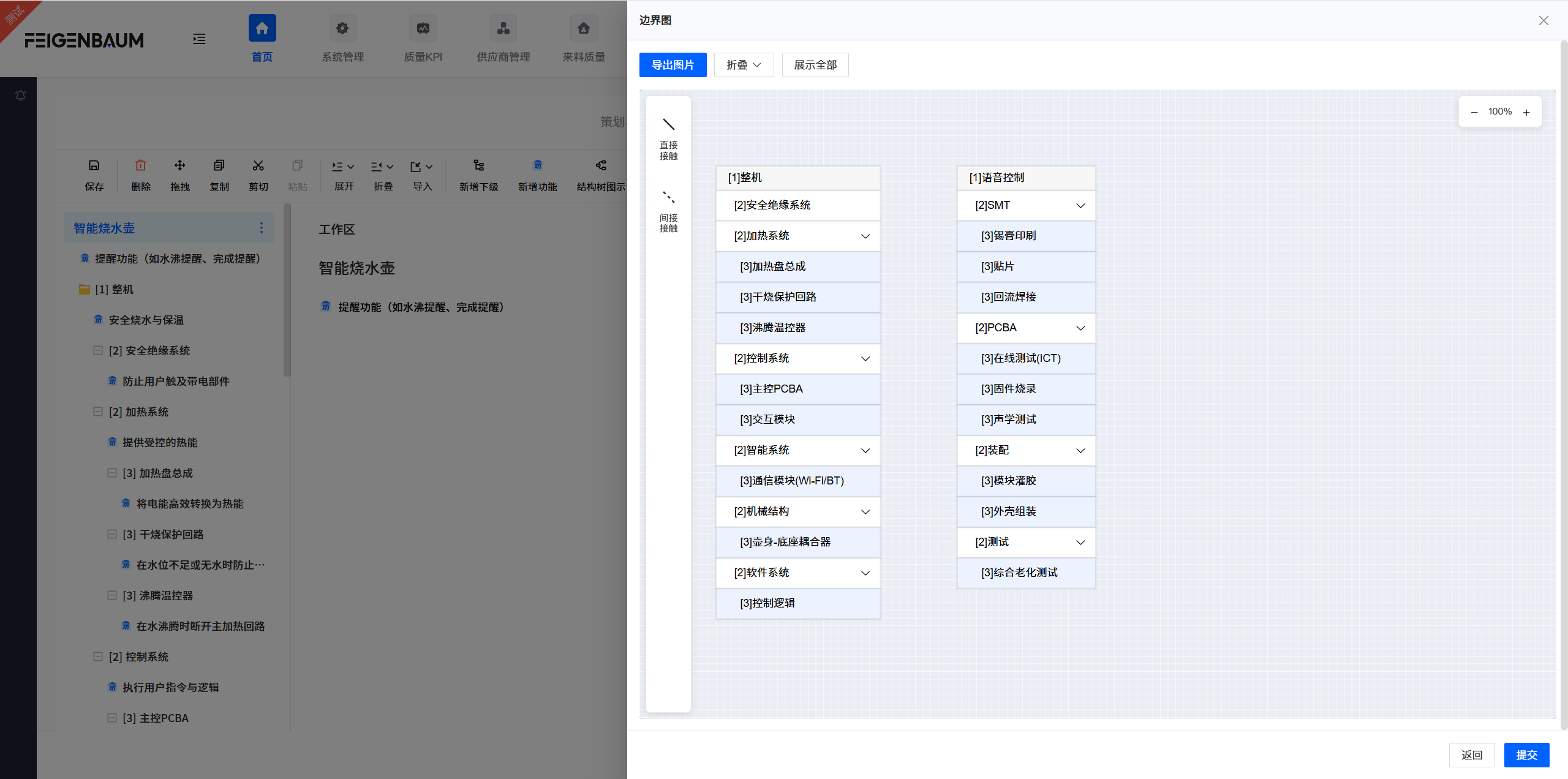
Block Diagram
Block diagram is a visual analysis tool used to define the scope of analysis and identify interactions between the system and its environment and adjacent systems.
Usage
- Use blocks to represent main components of the product.
- Use solid lines for direct contact interfaces, use dashed lines for indirect contact (such as gaps or relative motion).
- Use arrows to indicate direction of interaction.
Interface/Connection Types (PEIM)
Identify and annotate energy flows, signals, or forces flowing between components. Mainly divided into four types:
- P (Physical): Physical connections (such as welding, bolt fastening, clamping, etc.)
- E (Energy): Energy transfer (such as torque, heat, friction, electrical energy, etc.)
- I (Information): Information transfer (such as ECU signals, sensor data, etc.)
- M (Material exchange): Material exchange (such as coolant, exhaust gas, lubricating oil, etc.)